FPCB Industry News and Market Trends
Introduction to Rigid-Flex PCB
Flexible Printed Circuit Boards (FPC) and Rigid-Flex PCBs
Flexible printed circuit boards (FPCs), also known as flexible circuits, are high-reliability printed circuits made from polyimide (PI) or polyester films as the substrate. FPCs feature excellent flexibility, high wiring density, lightweight, thin profile, and good bendability. They are primarily used to connect with other circuit boards.
FPCs help save internal space in electronic products, making assembly and manufacturing more flexible. For example, in smartphones, the LCD/OLED or AMOLED display panels are connected via FPCs. FPCs are also widely used in laptops, digital cameras, as well as in medical, automotive, and aerospace applications.
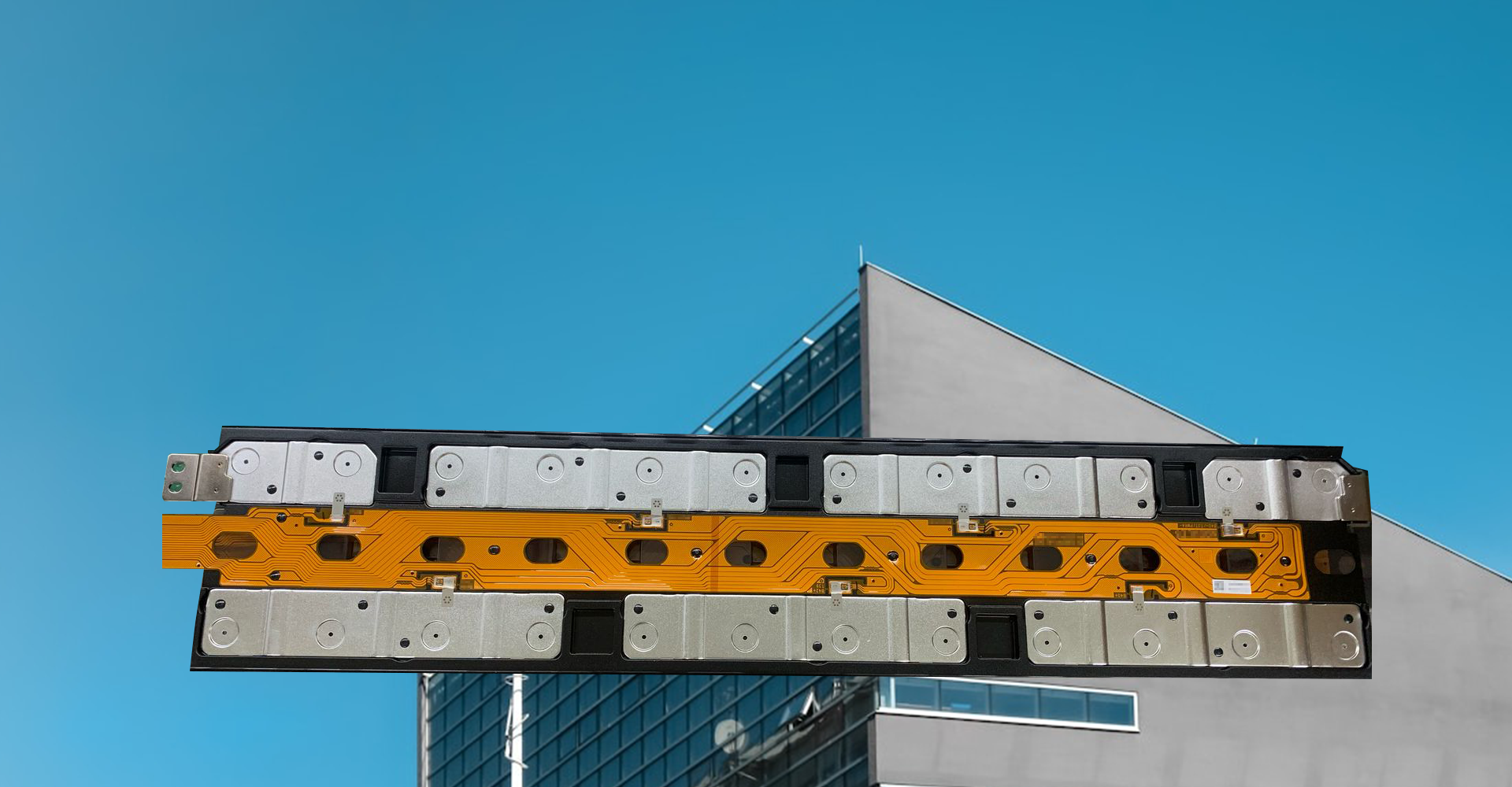
Rigid-Flex PCBs
Rigid-flex PCBs are boards in which flexible and rigid circuit boards are combined through lamination and other processes, following specific manufacturing requirements. They possess both FPC and PCB characteristics.
Rigid-flex PCBs provide dedicated flexible and rigid areas, making them ideal for products with special requirements. This design helps save internal space, reduce overall product volume, and improve performance. However, rigid-flex PCBs are more challenging to produce, have lower yields, are more expensive, and have longer production lead times.
Design Considerations for Rigid-Flex PCBs
Component Placement
Components should be placed in rigid areas; flexible areas should only serve as connections. This improves board lifespan and ensures reliability. Placing components in flexible areas can cause pad cracking or component detachment.
When placing components in rigid areas, maintain at least a 1 mm distance from the boundary between rigid and flexible regions.
Routing Guidelines
In flexible areas, circuit patterns should be at least 10 mil from the board edge, and no vias should be placed. Vias near the rigid-flex boundary should be at least 2 mm away.
Traces in flexible areas should be smooth; corners should be routed with arcs, and straight lines and arcs should intersect perpendicularly. Pads should include teardrop transitions to prevent tearing.
In bending regions, reinforce trace edges with copper foil at bends.
To maintain flexibility, avoid sudden changes in trace width or uneven trace density in bending areas.
Avoid overlapping traces on top and bottom layers in flexible regions to prevent stress concentration.
Have a design ready?
Contact us for a quick quote.